
Measuring HDMI Latency
by

Rob Wyatt
Managing display latency plays a big role in the architecture of game engines, video playback and display systems in general. In a typical consumer environment there is one component that we have little to no control over; the TV. Modern TVs and monitors have an unknown and undocumented latency between a frame being received and displayed - this is the latency we want to measure and in this post we are going to make a HDMI latency tester with a Raspberry Pi.
HDMI History Lesson
As usual with my posts… A bit of history
HDMI is a raster order, scanning format, in much the same way as NTSC or VGA. In fact HDMI has its roots in VGA. VGA consists of 3 analog signals, 1 for each of R,G and B, and 2 quasi digital signals for HSYNC and VSYNC. VGA has overscan areas in the signal, just like NTSC, and for the same reasons; mostly due to sync and settling time within the older analog monitors. As the display resolution increased, the bandwidth of the analog signals increased to a point where it barely worked, the result of band limiting analog video is a blurry image. Even with the best analog signal processing and the best cables, it was still blurry, the only solution was to switch to digital in the form of DVI.
Early DVI ports (DVI-I) carried the analog VGA signals along side the digital signals. The analog and digital signals had identical timing, the digital signal was taken before the DAC and the analog was after it. The structure and timing of the frame was the same between analog and digital, the digital signal had the same overscan areas and the same sync timing as the analog signal. DVI has no explicit sync signals. On any given pixel clock DVI encodes either pixel data or control data. The control data is limited to 6 bits and is transmitted as 2 bits per color channel, these bits are typically called C0 and C1. DVI only uses the 2 bits on channel 0 (the blue channel), where C0 and C1 are used to indicate HSYNC and VSYNC.
HDMI 1.0 is backwards compatible with DVI and it uses the same signalling on the 3 color channels, and the same sync information. HDMI 1.0 used the additional C0C1 bits on the red and green channels to mark video vs data, HDMI calls these video islands and data islands. Data islands are typically used to transmit audio but there are a handful of other things listed in the spec, data islands utilize the unused pixels within the overscan areas of the signal. HDMI 2.0 is an entirely different animal.
All the original DVI resolutions were PC-esq resolutions, things like 1024x768 or 800x600 and are typically called DMT (Display Monitor Timing) modes and defined by VESA. HDMI is quite strict in the timing it supports due to the sync areas being used for other things and defines a different set of modes more typical for consumer TV, resolutions like 1920x1080 and 1280x720 along with all the older NTSC/PAL resolutions, these are typically called CEA-861 modes as they are defined by the Consumer Electronics Association. The only difference between the two sets of modes is pixel timing, there is no flag to indicate its one of the other.
Lets look at some timing examples. For digital video one pixel is sent per clock cycle, horizontal timing is measured in pixel clocks, vertical timing is in lines. Using 1080p from the table below as an example: There are 2200x1125 total pixels, and at 60Hz this equates to 148.5 million pixels per second which happens to be the pixel clock rate.
| 3480x2160p60 | 1920x1080p60 | 640x480p60 | |
|---|---|---|---|
| Pixel Clock | 594 MHz | 148.5 MHz | 25.175 MHz |
| Pixel Time | 1.7 ns | 6.7 ns | 39.7 ns |
| Horizontal Freq. | 135.0 kHz | 67.500 kHz | 31.469 kHz |
| Line Time | 7.407μs | 14.815 μs | 31.778 μs |
| Vertical Freq. | 60.000 Hz | 60.000 Hz | 59.94Hz |
| Frame Time | 16.667 ms | 16.667 ms | 16.683 ms |
| Active Pixels | 3840 | 1920 | 640 |
| H Front Porch | 176 | 88 | 16 |
| H Sync Width | 88 | 44 | 96 |
| H Back Porch | 296 | 148 | 48 |
| H Blanking Total | 280 | 280 | 160 |
| Total Pixels | 4400 | 2200 | 800 |
| Active Lines | 2160 | 1080 | 480 |
| V Front Porch | 8 | 4 | 10 |
| V Sync Width | 10 | 5 | 2 |
| V Back Porch | 72 | 36 | 33 |
| V Blanking Total | 90 | 45 | 45 |
| V Blank Duration | 667 μs | 667 μs | 1430 μs |
| Total Lines | 2250 | 1125 | 525 |
| Active Pixels | 8,294,400 | 2,073,600 | 307,200 |
| Unused Pixels | 1,605,600 | 401,400 | 112,800 |
Visualizing the full frame for 1080p gives this:
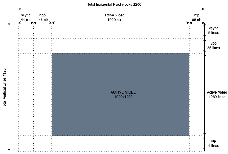
While none of this is directly relevant to measuring latency, it is important to know the full frame structure, there are significant portions that are not visible and need to account for them in any timing calculations.
A significant amount of data can be stuffed in the unused areas of the signal, especially for the high resolution modes. 4K has 1.6 millions unused pixels per frame, in theory this equates to 96 MBytes of data per second but the actual throughput is actually much less, especially on pre HDMI2.0, as data islands are sent at 4 bits per pixel clock per channel, and not all of the unused area can carry data. However it’s still a significant amount of data. Lower resolutions have fewer unused pixels and therefore can carry less data - 32 PCM audio channels are not possible on 640x480 video.
Where does the display latency come from?
The primary reason is because modern flat panel TVs support multiple input types with multiple resolutions and update frequencies, all of these inputs are decoupled from the native resolution and update characteristics of the physical display panel. The TV buffers the incoming signal to memory where it can be manipulated in software, it can be filtered, de-interlaced and scaled to native resolution independently of the input source or resolution. Color conversion and correction can be applied, Smart TV applications and on screen menus can be rendered on top, even other inputs can be overlaid as picture in picture before the final image is sent to the display. All of this processing takes time! While watching a movie the display latency isn’t much of a problem but for video games it can be a big issue when the display is lagging behind your button presses. In the early days of HD it was a problem for movies too because some TVs would delay the video but not the audio!
Why do some TVs take 10ms and some take 100ms is simply down to architecture of the display stack and how much it was optimized, along with how many pixels are being processed, what sort of processing is being done, how much of the display pipeline is hardware vs software. Some high end TVs have higher latency than you might expect simply because they do more processing on more pixels and processing power doesn’t scale the same. A lot of displays, especially TVs, have a game mode or low latency mode which is supposed to reduce end to end latency at the expense of some features being disabled.
Having a complete frame in memory, with all the pixels ready for display, is what enables a high end display to have 4ms update time - this time is just how long it takes the display panel to update and it can only update this fast if it has a whole frame ready. The fact the physical panel can be updated 4 times in the time it takes to receive one frame is where features such as 60Hz to 120Hz frame interpolation comes from. A modern smart TV is literally an embedded linux device that runs embedded image processing software nad has a capture card on the front end.
HDMI 2.1 has a few features to reduce latency, specifically Variable Refresh Rate (VRR) and Quick Frame Transport (QFT), which bursts a frame across the HDMI link at the maximum pixel clock supported (still in raster order). Utilizing these features, a TV that supports 4K60, should be able to transfer a 1080p frame in 4.15ms or a 720p frame in 1.85ms and still display at 60Hz.
In the old analog days there was no latency because the input signal directly controlled the raster beam of the TV. The typical latency of an analog TV was maybe a microsecond or two as this is how long it took for the input signal to propagate through the electronics.
TVs with buffering, image processing, and the associated latency are here to stay so lets measure it!
How do we measure latency?
In theory all we have to do is switch between a black screen to a white screen while timing how long it takes a phototransistor placed against the display to detect the white light (any two screens where you can detect the difference can be used, pure black and pure white are the easiest). In practice it’s a little more difficult because you need precise control of the display hardware because you need to know exactly where in the video signal you are, you also need a low latency IO system to which you can connect the photo transistor. On a typical PC there is no direct IO and USB will just add to the latency and make the hardware more complex. Without being in kernel mode and hacking around in the display driver its hard to know exactly what the display hardware is doing, outside of Linux you’ll probably never know what the display hardware is doing. A non-PC approach seems best.
My first attempt at measuring TV input latency wasn’t for HDMI at all, but for analog inputs, and I simply bit banged a composite NTSC signal on a miro controller; if you only need black and white this is pretty trivial. For HDMI bit banging is not so trivial because the bit clock is an order of magnitude greater than the pixel clock, the bit clock for 1080P is 1.485GHz. These speeds are out of the range of most FPGAs and very much out of range of software bit banging - although it has been done at lower resolutions with creative use of a RP2040. A lot of FPGAs have HDMI support and do all the serializing in a dedicated hardware, these tend to be expensive and even if they aren’t, they are complicated and require multi layer circuit boards. The goal of this project was for anybody to cheaply and easily measure latency. A simpler FPGA might not have HDMI blocks but could drive something like an ADV7511 HDMI encoder which takes parallel 24bit RGB pixel bus data. This did work all the way up to 1080p but it was a lot of complex hardware to simply output black or white.
Finally, I experimented with bare metal on a Raspberry Pi and after some experimenting it works awesome and I have a lot better understanding of how the Pi hardware works. The Pi also has lots of high speed IO making it trivial to interface with a phototransistor.
As an extra bonus, because the Pi can generate composite NTSC/PAL, and because these old analog formats use the same display hardware as hdmi, we can measure latency on the analog TV inputs with the exact same code!
Raspberry PI display hardware
For the rest of this article, I’m going to use a Raspbery Pi 3 B+ because its the one I had handy, however it can only output resolutions up to 1080p (maybe a little over if you overclock it). If you want to test 4K latency then at least a Pi4 would be needed and it will require code changes as the Pi4 hardware is slightly different. I’ll be using bare metal to keep the code as simple and clean as possible and we don’t have to fight with the operating system. Fortunately we can do everything with the display hardware and don’t need to deal with the complexity of the VideoCore GPU. To keep things even more simple lets use the standard boot code and configuration file to set the video mode and then hijack the hardware we need later. Using the boot code means there are only two display components we care about: Pixel Value (PV), and Hardware Video Scalar (HVS) and both are quite easy to understand.
By directly setting the video mode we can ignore what the TV says it supports via EDID. Your milage may vary but all the TVs I tried will display modes that are not listed in the EDID data. Monitors seem even more flexible. The old Dell U2713HM used for testing this project reports 1080p and 720p as the only HD modes supported over HDMI. However in testing it will display all the same PC modes that it supports over Display Port.
The example code for this project only supports HDMI and Analog SDTV, it does not support the other outputs such as DPI/DSI although its not a big change to support these. In addition to display hardware TIMER_LO is used as a micro second timestamp, although its a 64bit counter, only the bottom 32bits are used.
Pixel Value (PV)
PV is a hardware block that sits at the front of the encoders and counts pixel clocks to track where we are in the frame, whether we are scanning active or inactive areas etc. When scanning out an active area of the frame PV asks HVS for pixel data. The PV hardware only has a few registers, which we will read, but it will be programmed by the boot code to match the output encoder. The most useful thing that PV does for us is to generate interrupts for things like hsync, vsync, and most importantly, PV can generate an interrupt at the start of active video. Start of active video is when the first visible pixel is being output. From empirical testing there pretty much no latency between the PV indicating the start of active video and the pixels appearing on the HDMI signal.
When we switch from the black frame to the white frame, start of active video is the first instant the white pixels could be visible, this is when we start our timer and any delay before the white is visible is latency within in the TV!
struct pixel_valve
{
  volatile uint32_t c;            //bit2/3 control the clock src and which of HDMI/SDTV is being output
  volatile uint32_t vc;           //bit4 is set when interlaced
  volatile uint32_t vsyncd_even;
  volatile uint32_t horza;        //HBP and HSYNC clocks
  volatile uint32_t horzb;        //HFP and ACTIVE clocks (hactive is the width)
  volatile uint32_t verta;        //VBP and VSYNC lines
  volatile uint32_t vertb;        //VFP and V ACTIVE lines (vactice is the height)
  volatile uint32_t verta_even;   //same data as verta and vertb but for the even frame when interlaced
  volatile uint32_t vertb_even;
  volatile uint32_t int_enable;   //interrupt enables
  volatile uint32_t int_status;   //interrupt status
};

//The available interrupts are as follows (the horizontal interrupts are very high frequency)
#define PV_INTEN_HSYNC_START (1<<0)     //start of horizontal sync
#define PV_INTEN_HBP_START   (1<<1)     //start of horizontal back porch
#define PV_INTEN_HACT_START  (1<<2)     //start of horizontal active
#define PV_INTEN_HFP_START   (1<<3)     //start of horizontal front porch
#define PV_INTEN_VSYNC_START (1<<4)     //start of vertical sync
#define PV_INTEN_VBP_START   (1<<5)     //start of vertical back porch
#define PV_INTEN_VACT_START  (1<<6)     //start of vertical active (visible line0)
#define PV_INTEN_VFP_START   (1<<7)     //start of vertical front porch
#define PV_INTEN_VFP_END     (1<<8)     //end of vertical front porch
#define PV_INTEN_IDLE        (1<<9)     //idle
Although PV can generate interrupts, this project isn’t going to use actual CPU interrupts. We can keep CPU interrupts globally disabled, enable interrupts within PV which will cause it to update the interrupt status registert and then we’ll poll the interrupt status register to see what is going on. Polling should be much lower latency than handling an interrupt and there is much less jitter. We’ll use code like the following to wait for active video:
  while(1)
  {
    //volatile register - read it once so we see consistent data
    uint32_t stat = pv->int_status;
    if (stat & PV_INTEN_VACT_START)
    {
      //read the time in microseconds
      start_time = Read32(TIMER_LOW);  //read time from 0x3f003004;

      //clear status flags by writing 1's (this will clear all pending interrupts)
      pv->int_status = stat;
      break;
    }
  }
The above details show why its important to understand the video hardware as the structure of a frame. If we were to use vsync instead of active video for the start timer, and remember vsync is all that maybe available on some hardware, then a significant error correction has to be applied. At 1080p vsync occurs 41 lines before the first visible pixel, at 14.815us per line this equates to 607.414 μs. At 640x480 the time from the start of vsync to the first visible pixel is over a millisecond, 1112.23 μs to be exact! Fortunately the time between vsync and the first pixel is consistent so can be accounted for if the exact mode timing is known. Utilizing the start of active video interrupt is a convenient way of not having to deal with it.
The Pi3 has 3 different PV blocks, PV2 is the one that we’ll use as it drives both the HDMI and SDTV encoders. The others are for DSI/DPI displays supported by the Pi and all 3 PVs can be used at the same time and display different content.
Hardware Video Scalar (HVS)
HVS is DMA driven compositor and it doesn’t know anything about timing or output signals, it generates pixels on demand sends it to the PV for output, there are in effect 3 compositors within HVS, each drives one of the PVs. For HDMI and SDTV we shall use HVS channel 1.
HVS is maybe the most flexible hardware compositor I’ve ever seen on any video hardware, you could make a 2D game utilizing just HVS. It takes a display list that describes a set of frame buffers that make up the composition, the final composited result is not stored anywhere, it is onlt sent to PV to be ouput. The frame buffers that are composited can be any size, at any location on the screen, in different color formats, scaled, overlaid and alpha blended together. Each channel within HVS has a single register that sets the base address of the current display list. The display list memory lives in the HVS hardware and is only 4K in size, this 4K of display list memory is shared between all HVS channels currently in use.
A none scaled frame buffer only consumes 7 32bit words in display list memory so even if all PVs are enabled and outputting different content there should be plenty of memory to go around.
  //the fixed address of the 4K of dl memory
  volatile uint32_t* dlist_memory = (volatile uint32_t*)0x3f402000;

  dlist_memory[0] = //Control word/flags/format etc
  dlist_memory[1] = //x pos, ypos and alpha
  dlist_memory[2] = //width and height
  dlist_memory[3] = //dummy used by HVS
  dlist_memory[4] = //frame buffer memory address
  dlist_memory[5] = //dummy used by HVS
  dlist_memory[6] = //line stride bytes

  dlist_memory[7] = 0x80000000;   //end

  //display list for channel 1 starts at offset 0
  //this will take effect on the next vsync
  write32(DISPLIST1, 0);
The HVS hardware reads the display list register at the start of the next frame, any changes to the register don’t take effect until then. Changing the display list while its being used will cause problems.
For the HDMI tester one option is to have two precomputed full screen display lists, one that fills the screen with black and the other than fills it with white, then change DISPLIST1 to point at either the white or black list. This does work but there is a better way…Each HVS channel has a control block and in that control block are a number of very useful registers.
struct hvs_channel {
  volatile uint32_t dispctrl;
  volatile uint32_t dispbkgnd;   // xxRRGGBB, bit 24 is bg enable
  volatile uint32_t dispstat;    //0:11 line, 12:17 frame, 28 empty, 29 full, 30:31 mode
  volatile uint32_t dispbase;
};

//pi3 address for the hvs channel control blocks
volatile struct hvs_channel* hvs=(volatile struct hvs_channel*)0x3f400040;
The interesting registers are dispbkgnd and dispstat. dispbkgnd is the backgrounf color and is used for any pixels not covered by a buffer, if we have an empty display list then the whole screen will be the background color and the background color is a live register, it is sampled every time HVS generates a new line and can be changed on the fly outside of vsync. The bottom 12 bits of dispstat tells us what line HVS is currently generating. This counter has a quirk and it stops at active height when its finished generating the last visible line. This is super useful as when HVS has finished generating the last line we can make changes to the background color in plenty of time for it to be displayed next frame with changing what is currently displayed.
There is no official documentation on any of this display hardware, most of the above has been reverse engineered or derived from other projects. Addition information on HVS, PV, HDMI, SDTV and general bare metal programming can be found at the Pi version of little kernel, The Circle Project or the linux drm driver for VC4
Software
All the source code and build instructions can be found in our github repo
The basic idea is pretty trivial now the hardware is figured out. The basic outline is:
-
Obtain settings and display size from PV and HSV registers, we didn’t configure the mode so we’ll figure out what was configured by the bootcode and config file.
-
Set the background color to black for a few seconds to let things settle
-
Wait for HVS status to indicate the last line, change the background color to white which will be visible on the next frame.
-
Wait in a tight loop for PV status to show start of active scan out, take the starting time
-
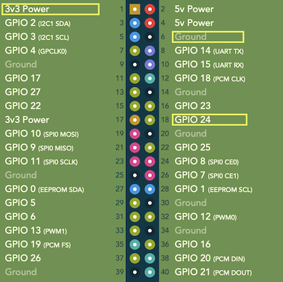
Wait in a tight loop for the photo sensor to pull GPIO 24 (pin18) low, this indicates the phototransistor has detected light, take a stop time stamp
-
Render the result to the frame buffer, turn the background back to black and repeat
Hardware
The only external hardware is a 100K variable resistor and a LTR-4206 phototransistor:
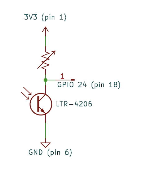
connected to the PI as follows:
The higher the resistance the more sensitive the transistor is to light, typically about 50k gives reliable results for a typical TV (a 50K fixed resistor could be used in most cases, I only used a variable resistor in order to tweak it). The LTR-4206 has a fairly narrow sensitivity window but it will detect ambient light from the sides which could give erroneous readings. The transistor needs to be shrouded so it only detects light directly in front of it. Electrical tape around the sides of transistor will work but you could also 3D print something more professional.
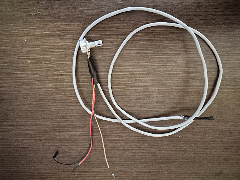
Here is a photo of my ghetto setup with the three leads that connect to the Pi.
You don’t have to use the LTR-4206, you can pretty much use any phototransistor but some aren’t great at directly driving a GPIO in this configuration, they work but output a voltage in the digital forbidden zone and results won’t be reliable. You need the voltage at the GPIO to be less than 0.8V (logic 0) when the transistor is detecting white, and above 2.5V when detecting black. Change the resistance to change the sensitivity. In the case where the phototransistor cannot be used directly, it can drive one input of a comparator while the other input is the reference voltage for detecting white from black, if the comparator is powered from 3.3V it can directly drive the GPIO.
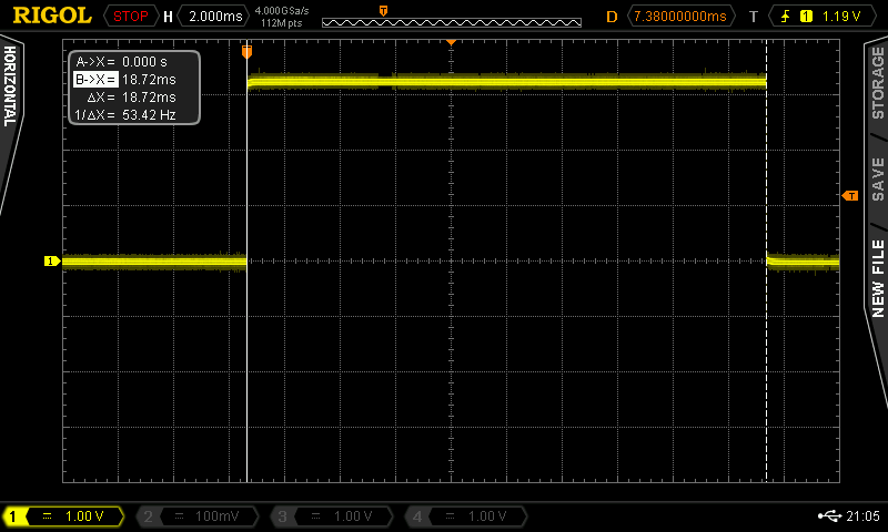
In addition to timing the latency in software, the example code configures GPIO 23 (pin16) as an output so latency can me measured with external hardware or oscilloscope. GPIO 23 is driven high at the start of active video and low again when GPIO 24 goes low, when the phototransistor detects light..
Results
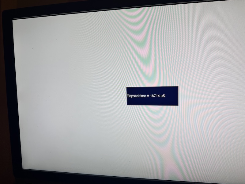
The black and white test screens aren’t using HVS display lists, only the background color, therefore we can use a display list to display a small buffer in the center of the screen with the results. The displayed result buffer utilizes dark colors to minimize ambient leakage any any affect the phototransistor. The result frame buffer stays away from the corners which are the locations where latency is most likely to be measured. Having the results displayed on the screen being tested makes the tester stand alone as no PC or additional hardware is required.
HDMI
The following test was performed on a Dell U2713HM 27-Inch Monitor receiving 1080P from the following Pi config and the phototransistor in the top left of the screen:
hdmi_group=1    #1=CEA, 2=DMT
hdmi_mode=16    #1080p60
The result is also output over uart (GPIO 14, pin 8) at 115200 baud, which can be received by a PC for logging.
Elapsed time = 18714 uS
Elapsed time = 18692 uS
Elapsed time = 18734 uS
On the same device with the phototransistor placed in the bottom right you see this particular Dell monitor has a display refresh speed of approximately 16.2ms.
Elapsed time = 34825 uS
Elapsed time = 34818 uS
Elapsed time = 34878 uS
However the input latency changes with the mode, changing the Pi config to hdmi_mode=31 (1080p 50hz), the input latency at the top right location increases to 28.78ms.
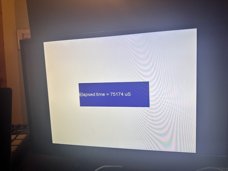
SDTV
The above HDMI tests were on a Dell PC monitor which doesn’t have composite inputs, I switched to a Vizio TV and thought I should retest the HDMI for reference. This particualar TV has almost identical performance to the Dell, about 18ms initial latency and about 16ms draw time. This will be the reference for the SDTV modes.
Setting PAL output with the following config option and remove the hdmi options:
sdtv_mode=2
The input latency is a whopping 75ms and the draw time is now 20ms which makes sense for 50hz. I can only assume the TV is waiting for multiple frames to run its de-interlacing algorithm. The 50Hz frame rate is probably not helping because NTSC at 60Hz does have better performance at 55ms but significantly higher than 1080p (which happens to be the panel resolution).
This same SDTV test on an old fashioned analog CRT would have latencies that are hard to reliably measure, it would be in single digit microseconds. Putting the SDTV from the latency tester through something like a RetroTink to convert back to HDMI will have much better performance and you can measure the latency of the converter itself.
Other PI hardware
Unfortunately this example code is 64bit bare metal so it will only run on a Pi3. However, there is no reason for it to be 64bit and it only uses a single core. The PV and HVS hardware from the earlier Pi’s is exactly the same. The assembly boot code and utils would need to be rewritten but the C code could simply be re-compiled for 32bit. With 32bit boot code it would be able to run on a PiZero and the total cost of this latency tester would be just a few dollars.
Pi4 and Pi5 still have HVS and PV but they are different. First of all they have more functionality and do things like color correction. Second, there are more units because there are more outputs. Adding support for the Pi4 would enable 4K and HDR output and the associated latency to be measured.
If anybody wants to add this support; feel free to submit a PR.
Nitty Gritty timing details
When you look closer at the line counter in the HVS stat register, there is a lot more going on than first meets the eye. For example, when outputting 1080p, the line number in the stat register goes from 0 to 1080 which is 1081 total lines… Why??? When does it go to 1080? When does it go back to zero? Does it stay on zero for longer than it should? What does the HVS do during the vblank? We can try to unravel some of this by simply logging how th various registers change. The code below spins against the current line in the stat register, taking a timestamp when it changes. It first records the data and then prints the results afterwards due to printf() using the UART and being generally slow.
  uint32_t line = hvs[1].dispstat &0xfff;
  uint32_t idx=0;
  uint32_t lines[2048];
  uint32_t times[2048];
  while(idx<2048)
  {
    uint32_t hw_line = hvs[1].dispstat & 0xfff;
    if (hw_line!=line)
    {
      uint32_t time = Read32(TIMER_LOW);  //0x3f003004
      lines[idx]=hw_line;
      times[idx]=time;
      line=hw_line;
      idx++;
    }
  }

  //the time stamp is taken when we start a new the line so the line time is from the current to the next.
  //Entry 0 might not be a full line, the last entry has no next, so ignore both the ends
  for (uint32_t i=1;i<2047;i++)
  {
    printf("Line %d - time %d [delta %d]\r\n",lines[i],times[i], times[i+1]-times[i]);
  }
We get some very interesting results…. Lines in the middle of the frame are really not interesting. Each line take 14 or 15uS which is the scan time of a 1080p line, the bouncing around is due to the timer having microsecond resolution and a 1080p line taking 14.815uS. I think its safe to assume HVS is outputting lines at the same rate they are being consumed by the HDMI encoder.
Line 38 - time 5915378 [delta 14]
Line 39 - time 5915392 [delta 15]
Line 40 - time 5915407 [delta 15]
Line 41 - time 5915422 [delta 15]
Line 42 - time 5915437 [delta 15]
Line 43 - time 5915452 [delta 15]
Line 44 - time 5915467 [delta 14]
Line 45 - time 5915481 [delta 15]
Around the end of the frame is where things get really interesting…What is going on between line 1080 and line 7 of the next frame??? After line 7 things go back to outputting one line every 14.815us
Line 1076 - time 11880867 [delta 16]
Line 1077 - time 11880883 [delta 14]
Line 1078 - time 11880897 [delta 15]
Line 1079 - time 11880912 [delta 14]
Line 1080 - time 11880926 [delta 103]
Line 0 - time 11881029 [delta 3]
Line 2 - time 11881032 [delta 3]
Line 3 - time 11881035 [delta 3]
Line 4 - time 11881038 [delta 3]
Line 6 - time 11881041 [delta 3]
Line 7 - time 11881044 [delta 668]
Line 8 - time 11881712 [delta 14]
Line 9 - time 11881726 [delta 16]
Line 10 - time 11881742 [delta 14]
Line 11 - time 11881756 [delta 15]
Line 12 - time 11881771 [delta 15]
Line 13 - time 11881786 [delta 14]
These results are incredibly consistent across multiple runs of the same configuration and if we time between line0 on consecutive frames its exactly 16.667mS (this conveniently verifies the accuracy of the micro second timer). Note there are some lines missing, in the above lines 1 and 5 are completely missing! At first I though it was a bug in the code related to loops running slower than expected because the caches are turned off, but the time stamps don’t indicate anytime is missing. The stat register never contained those line numbers and I don’t know why, but I do know if lines take more time generate then they are not skipped by the stat register..
Whatever HVS is doing fits exactly in a frame.. Its also interesting that Line7 takes roughly the same time as the 1080p vblank period. Lets compare the VFP (Vertical Front Porch) and VACTIVE (visible video) of PV against the line number in HVSe, as expected it occurs during 7 at 1080p and line 18 at 480p. In reality we don’t care what the HSV line is, we’ll simply start the timer as soon as we see vertical active.
  while(1)
  {
    uint32_t stat = pv->int_status;
    uint32_t hw_line = hvs_channels[1].dispstat & 0xfff;
    if (stat & PV_INTEN_VACT_START)
    {
      pv->int_status = stat;
      printf("%d\r\n",hw_line);
    }
  }
The above code running in 1080p indicates HVS is on line 7, the line that matches the vblank time, when active starts. This does tell us a critical piece of information: We can’t rely on HVS line 0 for the latency tester because this occurs at the end of the previous frame. The line number in HVS is the line it is currently generating and not the line currently being scanned out, and we must use PV to detect the start of active video. While we can detect the area of active scan out by looking at the timeing, we can’t do it reliably for any video mode.
The code below is identical to the code above but waits for Vertical Front Porch, which is also the end of active video from the previous frame…This code will print HVS is on line 0 at VFP….
  while(1)
  {
    uint32_t stat = pv->int_status;
    uint32_t hw_line = hvs_channels[1].dispstat & 0xfff;
    if (stat & PV_INTEN_VFP_START)
    {
      pv->int_status = stat;
      printf("%d\r\n",hw_line);
    }
  }
Here is what I believe is happening… HVS starts generating the next frame at the start of the vertical front porch, this gives it the entire vblank period or 667uS, to get a head start. It needs to get a head start because the work load on each scan line isn’t consistent, it depends on what buffers cover which scanlines, how they are blended etc - HVS is basically a big DMA engine. In the above timing there are no buffers, only the background color, so it should be as fast as possible and HVS generates the first 7 scan lines in 15us. It appears there is a working FIFO that can hold 7 1080p scan lines, when HVS gets to line 7 it can’t generate it because there is nowhere put it so it has to wait until line 0 has been sent out, which won’t happen until active scan out, therefore it has to wait for the remainder of the vblank and for line 0 to be sent out. After this one scan line becomes free in the FIFO every time one scan line is sent to the TV encoder, this occurs every 14.815uS, hence why the following lines are spaced at line interval. The actual line only takes HVS 2-3uS to generate but it has to wait because the FIFO is full. What is the time spent at line 1080? I beleive this is how long it takes to empty the FIFO. When the HVS gets to line 1080, it still has 7 lines in the FIFO that need to be scanned out. 7 lines at 14.815uS each is 103.7uS which is how long it was on line 1080..
In the above timing, line7 taking 668 uS which is pretty much the exact length of the vblank in 1080p, is a fluke. Line 7 has to wait for the end the vblank+1 scan line or 14.815us, in this example it just happens to be that the first 7 scanlines also took 15uS.
What happens if we change the display resolution, to say 720x480 with a line period = 31.778uS
Line 475 - time 87363732 [delta 33]
Line 476 - time 87363765 [delta 31]
Line 477 - time 87363796 [delta 32]
Line 478 - time 87363828 [delta 32]
Line 479 - time 87363860 [delta 31]
Line 480 - time 87363891 [delta 590]
Line 0 - time 87364481 [delta 3]
Line 3 - time 87364484 [delta 2]
Line 6 - time 87364486 [delta 3]
Line 9 - time 87364489 [delta 3]
Line 12 - time 87364492 [delta 2]
Line 15 - time 87364494 [delta 3]
Line 18 - time 87364497 [delta 1426]
Line 19 - time 87365923 [delta 32]
Line 20 - time 87365955 [delta 32]
Line 21 - time 87365987 [delta 32]
You get the same pattern as 1080p but the timing matches the frame timing of 480p. It now blocks until the end of vsync on line 18 and not line 7, this indicates the FIFO is of a certain size in pixels and not a fixed number of lines.. A 1080p frame is 1920 visible pixels/2200 total pixels and the FIFO held 7 lines, a 720x480 is 858 total pixels and the FIFO held 18 lines, the FIFO is something like 16K pixels. Trying other resolitions confirms this.
Whate does HVS do when the output is interlaced?? The timing below is from composite NTSC with 64us lines:
Even field
Line 570 - time 40490252 [delta 64] [frame 45]
Line 571 - time 40490316 [delta 3] [frame 45]
Line 572 - time 40490319 [delta 61] [frame 45]
Line 573 - time 40490380 [delta 2] [frame 45]
Line 574 - time 40490382 [delta 62] [frame 45]
Line 575 - time 40490444 [delta 2] [frame 45]
odd field
Line 267 - time 40500557 [delta 63] [frame 46]
Line 268 - time 40500620 [delta 3] [frame 46]
Line 269 - time 40500623 [delta 61] [frame 46]
Line 270 - time 40500684 [delta 3] [frame 46]
Line 271 - time 40500687 [delta 61] [frame 46]
Line 272 - time 40500748 [delta 2] [frame 46]
HVS processes all the lines but only generates output for the lines needed on the current field, each pair of lines takes 64uS due to filling the FIFO. If you are looking at HVS regsiters an interlaced frame will look very similar to a none interlaced frame.